Friday, March 23, 2018

Validating air data probe battery life – with data

Hello, world!

I've been hard at work on several aspects of Airball's air data sensor probe as well as the in-cockpit display unit. I recently received circuit boards for version 4 of the sensor probe. This new board fixes a lot of things, and adds several new bits of functionality... which I'll cover in another post. One of the things it adds, though, is a battery monitor chip (the Maxim DS2782), so we can now monitor the probe's battery status in real time.

Since I am now able to easily get high resolution battery voltage and current, it seemed like a good time to do a battery "rundown" test, and collect useful data. I wanted to validate a few things:
  1. The total useful runtime from a full charge. I had some ideas about what it ought to be, but I wanted to confirm that the math is not too far off base.
  2. How the probe behaves as the battery voltage drops.
  3. Whether the probe will safely cut off at any point, or just keep running and potentially damage the battery.
  4. Whether the battery monitor chip is working and sane.
The test went well, overall! For this test, I was using a 1 Ah LiPo battery from SparkFun and a XBee Pro 60 mW 802.15.4 radio. Here is the data collected:


Using this combination of battery and radio yielded at least 12 hours of usable runtime on a full charge – quite acceptable! And, the battery discharge curve looks exactly like it should for a LiPo battery. So I must be doing something right...

A few things still require follow-up, of course:

  • The runtime was actually longer than expected (we expected ~7.5h, but ran for about double that). The battery discharge rates (in both mA and mW) we saw aligned reasonably well with our predictions, but the battery capacity seemed to be much higher. I am not sure whether that is due to the battery cell having a higher capacity than advertised (maybe?!), or some other problem with the test setup, but more validation is needed.
  • Neither the battery itself nor any other component cut off the module at a safe low voltage level. (The battery should have a low voltage cutoff at 2.75V, but despite allowing it to discharge to 2.6V, it never cut off...) I will add some additional protection mechanisms (both software and hardware) to avoid over-discharge of the cell.
More to come soon about these air data probe improvements, and some brand new design work on the display unit!
Tuesday, March 13, 2018

Yaw consistency in flight test

Here we will analyze the yaw consistency of the flight test in this directory:

https://github.com/airball-aero/airball-embedded/tree/master/data/2018-03-09-01

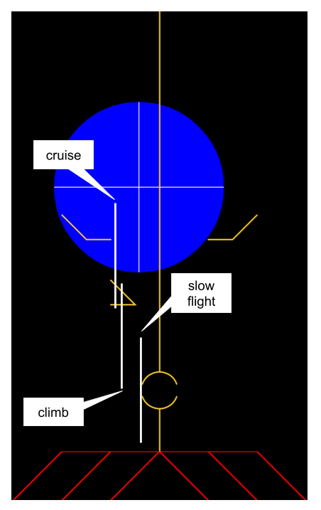
Recall that we observed the positions of the Airball yaw indication, with the inclinometer centered, at the following locations:


The display is 480 px wide, so half of it is 240 px. We know the pixel sizes of the decorations -- they are laid out on a 20-pixel grid. And we know that full scale beta was +/- 15 degrees. So we can approximate the yaw angles that our probe computed at these conditions as:

cruise: (2.75 * 20) / 240 * 15 = 3.4 degrees
climb: (2.5 * 20) / 240 * 15 = 3.1 degrees
slow flight: (1 * 20) / 240 * 15 = 1.3 degrees

The total variation in yaw between cruise and slow flight is therefore (3.4 - 1.3) = 2.1 degrees.

Assuming that we did indeed center the ball properly in all conditions, this means we should expect, at that mounting location, to read about 2 degrees of yaw error as a result of speed variation.

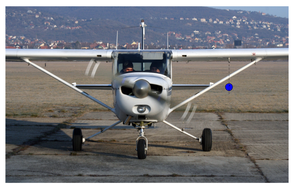
Recall that this is with a "bad" mounting location that is really pretty close to the prop slipstream -- in fact, closer to the slipstream than the factory Pitot tube itself:


So for the Nth time, the question we're trying to answer here is: Is it a good idea for Airball to measure the angle of yaw directly, or is the flow near the airplane too disturbed, and should we instead settle for something like lateral acceleration normalized by our best guess of the free stream dynamic pressure?

My conclusion from this data is that we don't yet know. :) We should:

1. Try another test with the probe mounted farther outboard -- perhaps mounted a little distance vertically below the intersection of the strut and the wing.

2. In flight, play with the relative sensitivity of the Airball yaw measurement compared to the inclinometer ball, since theory says that, with reduced dynamic pressure, the inclinometer should get "mushy". Verify that the yaw deviation seen at slow flight is real.

3. Acquire some data where we correlate the probe inputs with a signal from an accelerometer. This should eliminate the pilot technique issues of trying to center the inclinometer then read the Airball location.

This should give us a bit more information to either validate our direct yaw measurement, or nudge us to do it indirectly instead.

Second flight test

We conducted a second flight test, in a Cessna 172M. The data folder is here, with lab notes included. We will be adding some blog posts about the interpretation of the data soon.

https://github.com/airball-aero/airball-embedded/tree/master/data/2018-03-09-01

Friday, March 9, 2018

Open Source!

We've been busy with this and that since our test flight, but we haven't blogged much. Rest assured, more news is on the way. We're hard at work on new probe mechanical parts and electronics, a new display, and a more powerful wireless connection.

But we do have a HUGE milestone for you: Our code is now officially Open Source under the MIT License! Check it out here:

https://github.com/airball-aero/

We are not yet quite sure of the best way to release our mechanical designs -- these are scattered around in SolidWorks, OnShape and Autodesk Fusion 360. But we're working on that. Otherwise, everything else about Airball, including Eagle files for our circuit designs, is in the repo!