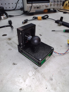
The C++ hacking I described in my last blog post was to clean up the event queue in the code so that I could reasonably add some input devices, namely, an adjustment knob. I now have that working. Let's see how this came together....
First the interesting part. Here is the new display (which you might note is 1/2" shorter due to the better positioning of the display connector). It is connected to an Adafruit Rotary Trinkey via a generic USB hub. Imagine that the display is mounted on the glareshield of an airplane somewhere, while the rotary knob is accessible on the panel or in some other easily reachable location. Note how I use the knob to adjust the barometer setting, and (finally! woo hoo!) the LCD panel brightness:
The display board, like its predecessor, is very unassuming -- other than having the correct backlight LED driver part (duh!):
The mounting is via a RAM ball on the back, as with the previous one:
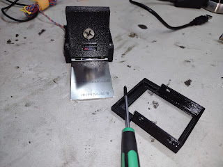
In designing where the flex circuit was to come out, I ended up putting it on the same side as the SD card on the RasPi, meaning that the LCD panel covers the SD card. This required some trickery to make the bezel removable for access to the card. In the end, this was probably not a bad compromise. It leaves the other connectors free for use.
Overall, this is a big step forward and likely my last iteration of this design until we go to a truly custom and truly mini board with a Raspberry Pi Compute Module 4. Stay tuned for that!


No comments :
Post a Comment